
http://www.thedailygreen.com/cm/thedailygreen/images/bug-zapper-TP-med.jpg
I knew that to make this more of a challenge I needed to have some game elements that could kill the player. One thing I really wanted to have in there was an electrified surface, which would zap the player, who then would disappear in a puff of smoke, like a fly on a bug zapper.
 1. Created a plane.
 2. Extruded down along the Y axis.
 3. Created a cylinder along with a couple of subdivisions on both ends.
 4. Extruded out the face loops, to create some sockets for the tubes.
 5. Created a simple cross shape in Photoshop.
 6. Added gradient overlays, to create a more 3-dimensional feel.
 7. Defined these as a pattern, filled the layers with the pattern and exported them as a .png.
 8. Got some strange import results in Unity, so just imported them as .psd files to get the alpha channels right.
 9. Altered the specularity settings on a transparent, diffused specular shader in Unity, to create a metallic mesh look.
 10. Exported the model of the electric box into Blender from Cinema 4D ad started marking seams on the model, to be unwrapped for the UV layout.
 11. Blender's unwrap function is really effective and useful, however it sometimes distorts islands needlessly, even if they are symmetrical or identical.
 12. I manually aligned a lot of the vertices to be more rectangular.
 13. In Photoshop, I used the exported .tga of the UV layout and blocked out the colours of the mesh.
 14. Because I wanted the tubes to "glow" I added a self illuminated shader to the object in Unity. This gave some very undesirable and cartoon-like results, so I went back into blender and exported the tubes, separately from the rest of the model and reimported them to have separate materials.
 15. Giving the main part of the box a reflective shader, gave the model a nice metallic look.
 16. That combined with the mesh I had created previously, made the object really start to come together.
 17. I then added a blue tinted light to add to the glow.
 18. I then used some of the procedural examples from the Unity website's example projects (http://unity3d.com/support/resources/example-projects/procedural-examples) to make an electric particle effect. This took a lot of tweaking, removing unnecessary scripts, altering the mesh render settings of the target and emission points and changing the general scale and randomness of the system.
 19. Finally, I wanted to try and add some visible electricity onto the surface of the object and had started looking into using animated textures and found a useful script on the Unify Comminity's wiki (http://www.unifycommunity.com/wiki/index.php?title=Animating_Tiled_texture), which allowed an object's texture to be animated based on a tiled image.
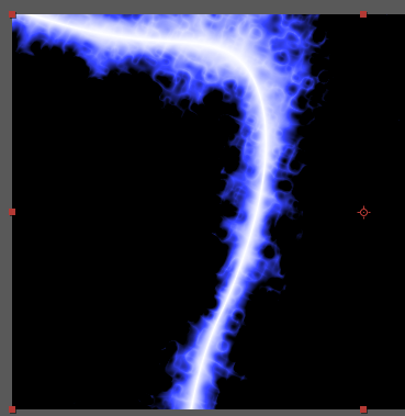
So I went into After Effects and searched for "electricity" and "lightning" in the presets and found a preset called "lightning bend".
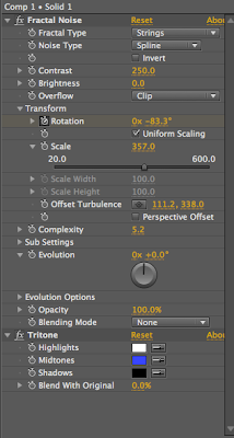
 20. I altered the midtones to a be a blue colour.
 21. I then altered the blur for a less pixelated effect.
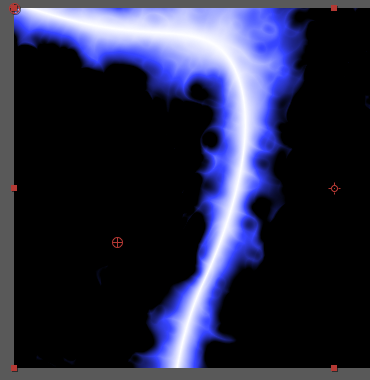
 22. I then resized the effect so that it would look better over the mesh.
 23. I added some key frames for rotation and tried to make it so the effect would loop fairly well and look as seamless as possible.
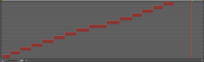
 24. Because it still looked a little bit too uniform in its movement and not as random asI would've liked, I split the clip up and staggered them about, however this looked a bit too much like clips cut together so I reverted back to the single clip and instead, altered the evolution level of the fractal noise, which looked much more lively than the previous version.
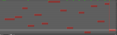
 25. I exported the cropped composition as a png. sequence and changed the output channels from "RGB" to "RGB + Alpha" to export the transparency. I also needed to compromise on size and frame rate, because although it would have been nice to have each frame 1024x1024 and run at 25 fps, this would've meant that the actual texture png file would need to have over 130 million pixels, which would be impractical and impossible. I instead decided to opt for 5 fps and a resolution of 256x256, meaning I could create a simple 1280x1280 image, with each frame laid out on a 5x5 grid (1.6 million pixels).
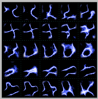 26. So I laid each frame out on the grid in Photoshop and discovered that some of the black add been exported with the composition, so rather than go back and re-export, I decided to correct this in Photoshop.
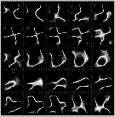 27. I duplicated the layer and desaturated all of the colour out of the image then copied and pasted this grayscale image into the alpha channel of the coloured layer.
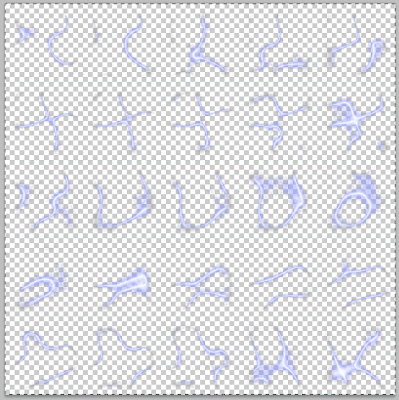 28. This was the result. I now save this as a .psd, imported into Unity and attached the AnimatedTextureUV.js from http://www.unifycommunity.com/wiki/index.php?title=Animating_Tiled_texture, to create a nice animated electricity effect to overlay on my existing electrified box.
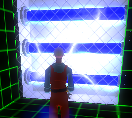 27. To complete the illusion of a high voltage electric hazard, I added a generator sound clip from http://fxhome.com/sounds/ and adjusted the roll off, so that the electric buzzing sound became louder, depending on how far away the player is from the electricity. This really completed the effect.
 20. I altered the midtones to a be a blue colour.
 21. I then altered the blur for a less pixelated effect.
 22. I then resized the effect so that it would look better over the mesh.
 23. I added some key frames for rotation and tried to make it so the effect would loop fairly well and look as seamless as possible.
 24. Because it still looked a little bit too uniform in its movement and not as random asI would've liked, I split the clip up and staggered them about, however this looked a bit too much like clips cut together so I reverted back to the single clip and instead, altered the evolution level of the fractal noise, which looked much more lively than the previous version.
 25. I exported the cropped composition as a png. sequence and changed the output channels from "RGB" to "RGB + Alpha" to export the transparency. I also needed to compromise on size and frame rate, because although it would have been nice to have each frame 1024x1024 and run at 25 fps, this would've meant that the actual texture png file would need to have over 130 million pixels, which would be impractical and impossible. I instead decided to opt for 5 fps and a resolution of 256x256, meaning I could create a simple 1280x1280 image, with each frame laid out on a 5x5 grid (1.6 million pixels).
 26. So I laid each frame out on the grid in Photoshop and discovered that some of the black add been exported with the composition, so rather than go back and re-export, I decided to correct this in Photoshop.
 27. I duplicated the layer and desaturated all of the colour out of the image then copied and pasted this grayscale image into the alpha channel of the coloured layer.
 28. This was the result. I now save this as a .psd, imported into Unity and attached the AnimatedTextureUV.js from http://www.unifycommunity.com/wiki/index.php?title=Animating_Tiled_texture, to create a nice animated electricity effect to overlay on my existing electrified box.
 27. To complete the illusion of a high voltage electric hazard, I added a generator sound clip from http://fxhome.com/sounds/ and adjusted the roll off, so that the electric buzzing sound became louder, depending on how far away the player is from the electricity. This really completed the effect.


 The next method I used was adding a MouseOrbit script from the Unity standard assets to the camera and the setting the 3rd person controller as a target. Already this felt much nicer as the character could been seen and the mouse could be used to look around the world. One problem with this was that default camera distance was quite far away, so I needed to experiment with the distance variable of the script to get a better view point.


 7. I set a UV test image as the background and adjusted the UV layout, so that they reflected their size. I had to spilt the wooden parts in half and rotate 1 side of them, so that when it came to texturing them, I could still make the texture seamless, even though the sections were side by side, rather than one continuous shape. I also deliberately left a squared space in the top left hand corner, so that I could add a texture for another object on the same image file, probably the floor tile, which accompanies the wall.

 8. Exported the UVW as a TGA file, soI could use it as a reference for creating the texture. Because the wood will be fairly unnoticeable on the model, I decided to just use a downloaded wood grain texture from SweetSoulSister's deviantART page. For this texture I just used thesame methods as I used for the floor, a combination of copying, pasting, transformation etc. and using Filter Forge to create the normal map. http://sweetsoulsister.deviantart.com/gallery/23627621?offset=0#/d2ez3p7